Monday, April 19, 2021

A new addition to the collection - The Oric Atmos

I never had an Oric growing up. In fact I'd never heard of them - my world was a sheltered bubble of ZX Spectrums, Commodore C64s and Amigas, and the odd Atari console I vaguely remember playing on round a friends house and scoffing at the "backwards" graphics (whilst secretly really wanting to play Ghostbusters one more time).


However, a lucky eBay auction later where I am the only bidder landed me with this little beauty. 


Meet the Oric Atmos - a relatively rare 48k alternative to the zx spectrum from 1986 that just missed out on being popular. This computer sold well in France, and used a 6502 processor like the c64. This one is mint condition, boxed, and came with several useful books and (not so useful cause they don't work) cassette tapes - purchased on eBay of all places. Who'd have thought?

Fun fact: one can be seen in the background of the IT crowd on one of the shelves. No, not this one.


Machine specs:

Model: Oric Atmos

Memory: 48K (well, 64k actually but that's taken up by BASIC and needs hacking to get at)

CPU: 6502 @ 1Mhz

Sound: AY-3-8912

Cost: £150 from ebay


So, now all I need is a joystick expansion and something to load games into it that doesn't take 500 years to load and crash out half way through..

Wednesday, April 7, 2021

Building a c64 PSU part II


So as we left it, we should have something like you see in fig. 1, the mains side of the PSU is wired up with the fuse and the optional lamp.

On to the tricky bit!

I was lucky, and had an existing DIN connector from an old non-functional c64 power supply that came with the c64 I bought from eBay, but you may not be.

You can find the DIN connector here, and any 5mm diameter cable that has 4 "cores" that have about 1.5mm diameter wires inside it should be sufficient, such as this one which I will be using for reference.

Step 1: Assign your coloured wires to what they are going to do. So, in our example cable we have blue, brown, black and yellow/green striped cables:


  • Black wire will be +5v
  • Green/Striped will be -5v
  • Blue 9v AC
  • Brown 9v AC (doesn't matter which way around these go)

Step 2: Push the wire through the hole. Solder all the wires in to their respective terminals (with heat shrink!); the +/-5V are the most important to get the correct way around. They are labelled, if you're using the PSU I specified in part 1, as +Vo and -Vo. If you are using an LED, put two lots of heat shrink (one small, one big) on the -ve 5v wire, this will be used to cover the resistor legs.


Step 3: (Optional) The LED needs some juice, in our example around 2v and around 10mA forward current from the 5v supply for red LEDs. Solder one of the legs (you may want to trim them first) of the 300 Ohm resistor to the negative terminal of the 5v PSU. Put enough heat shrink on so that it will cover the bare leads of the resistor, and then solder some wire between the negative leg (usually the shortest leg) of the LED to the end of the resistor.

Step 4: Solder some wire between the +ve terminal of the LED and the +5v connection on the PSU. The positive leg of the LED is usually the longest. Pop the LED into its hole.

Step 5: Fit the DIN cover over the wire before you connect to the pins.

This is the main tricky part, soldering the other end of the cable to the right DIN connectors. It helps here if you have some helping hands but they are not essential. Here's another blog explaining how to do this in more detail, it's fiddly! Solder, in any order;

Pins with colour coding

Pin 5 to the black cable (+5v)

Pin 2 to the green/yellow striped cable (-5v)

Pin 7 to the blue cable (9v AC)

Pin 6 to the brown cable (9v AC)


source: www.retroleum.co.uk


Testing is tricky, the DIN connector is not really great for sticking probes in to so be very careful - its best to check without the hood of the din connector on. However, even if you have stuck the hood on, you should be able to check with your multimeter that you have 5v on pin 5, 2 and 9v AC (remember to put your multimeter in AC mode!) It's essential to check you have the right values at the right pins, cause any mistakes and your C64 could be damaged.

Step 5 is to fix the DIN plug's hood snugly over the pins, and affix in whatever way your particular DIN connector affixes. Then heat shrink all your heat shrinks if you're happy!


And thats it! I hope you now have a decent PSU for your Commodore 64.


Friday, April 2, 2021

Restored £60 ZX Spectrum

Bought on eBay 2019, and restored early last year (2020) sometime, this little zx spectrum's life had been a hard one.

It became even harder when I applied my inexperienced cag-handedness to the situation. Believe me, don't practice soldering on something this age.. it's just too delicate!

It was the first one I'd ever done, and was a huge learning curve. Since it was so long ago, and I have pretty much forgotten everything I had to do to figure out what was wrong with it, I'm recording the bill of work done to it here for posterity.


Model: ZX Spectrum 48k

Board: issue 3B


  • Replaced the ULA with retroleum Nebula
  • All lower memory socketed 
  • Broken traces fixed damaged when I removed the lower ram
  • Two PCB through holes fixed damaged whilst removing the lower ram
  • Recapped
  • Traco 5v switching regulator (can't remember the amps)
  • Composite mod added
  • Replacement face plate
  • Retouched logo

These  ZX Spectrum boards really are a piece of artwork to my mind, and the black caps and black nebula board only add to the beauty.

I hope you agree!


Thursday, April 1, 2021

Building a c64 PSU

PSU in action - you too can build this!

After watching the amazing Jan Beta build a c64 PSU from bits, effectively cobbling a 5v PSU and a 9v transformer together, I thought I'd give it a go myself.

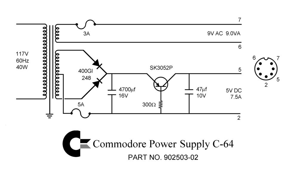
The c64 is that iconic 8bit computer we all loved back in the eighties. It has a very odd PSU which delivers both 9v AC and 5v DC to the main board, and pretty much nothing I've seen in the modern world (that isn't specially made) can deliver this Frankenstein requirement.

Enter Jan's lazy method!

WARNING: I do not take responsibility for you electrocuting yourself when you are doing this. Only proceed to do this if you are comfortable and competent at working with mains voltages!!

We won't be measuring the mains voltages so nothing fancy is required, but you need to know the basics of how to use a multimeter properly. And how not to die electrocuting yourself. 

My own Lazy Method:

You will need:

  • XP Power, 10W AC-DC Converter, 5V dc, Encapsulated (RS Component Stock no.:172-0797)
  • PCB mount transformer 9v 25VA 1x9 o/p (RS Components Stock no.:732-0471)
  • Red neon Indicator, Lead Wires Termination, 240 V, 6.4mm Mounting Hole Size (RS Components Stock no.:576-608) (optional)
  • Terminal connector block (only need 2 pair, 16 is surplus!) 
  • A suitable project box - I chose this one
  • Some spare mains cabling
  • A mains cable with a plug attached
  • A couple of cable grommits the same size as the cables to stop the cables from slipping and that covers the holes where they come through.
  • Epoxy resin (to glue down the components) or hot glue
  • A multimeter
  • Some heat shrink tubing
  • A fuse holder for a standard 1 amp fuse (or lower rating, 0.5 amp would be ok)
  • At least a 1 amp fuse
  • A red LED (optional)
  • A 300 ohm resister (to dissipate the power from the 5v supply to the LED if you are using one)
  • An 7 pin DIN adapter and suitable cable - I had an old one from the c64 I bought where the PSU was broken
  • Soldering skills (solder, a soldering iron, tough skin for burns)
  • A drill and a variety of bits (to put holes in the case)
  • RCD socket like this one
  • A good multimeter
We are using the terminal block to separate the mains side from the transformer and converter, because if one of the them blows we can just remove them and replace them with another, without having to desolder the parts in the future. See? Forward thinking. I didn't know I had it in me :)

Step one is to drill your holes in the case. You can work out the placements for the holes yourself, your mileage may vary. There should be: 
  • Two holes in the "front" of the project box, one for the cable that goes to the computer and one for the LED
  • Three holes in the rear, one for the cable, one for the fuse holder and one for the neon lamp
I'm not going to give measurements, but sufficed to say the bits you use to drill the holes should match the size of the component that will go in the hole!

I do suggest, however, you put the holes in the base of the project box only. This is so when you open the box for maintenance (or other general faffery), you don't have the hinderance of wires being connected to the top of the box.

Step two is to run the mains cable into the box and secure it by tying a knot. Don't forget to put the grommet on, ready to be pushed into the cable hole. Connect the blue (neutral) lead to the connector block. 

Step three, fit the fuse holder in its hole, and connect the live cable to the top connection on the fuse holder by soldering with lots of good solder and plenty of flux. Don't forget to twist the cable and tin it before you connect it to the fuse connection, and add a heat shrink tubing to the wire on the fuse end. Don't shrink the tubing unless you are sure of the position the cable is in, its much harder to change things if you do.

Step four, use a longish piece of brown (UK live) mains cable to connect the other fuse connector (the one you didn't connect the mains cable to) to the connector block. You will have to solder on the cable to the fuse connector in a similar manner to step three. Don't forget some heat shrink tubing, although this one isn't such an issue because you can unscrew the terminal to add it if you forget.

Step five, screw in the neon lamp to the terminal connector on the mains side. Push the led through the hole you made and screw it in place if you so desire.

Fig. 1 - Partially complete!
Step six, connect some well lengthed mains cables (live and neutral) from the other side of the terminal connector block to their respective connectors on the  9v ac transformer. This should be the same colours going in to the terminal block as going out! (In the UK brown for live, blue for neutral). You should  solder on the wires to the 9v AC transformer using plenty of solder and a tinned wire, respecting the correct connection for neutral (usually marked with a "0") and live (unmarked? check this). Remember again to add the heat shrink!

Step seven, connect some well lengthed mains cables (live and neutral) to their respective terminals on the 5v AC/DC converter with tinned wire and plenty of solder again. Yep, don't forget the heat shrink!

Fig. 2 - Testing 
Phew! That's the first part done, the part with the mains AC is the most important to get right. If ok, you should end up with something like in figure 1 and 2. Congrats, we're half way there!

Now it's important to check everything at this stage, and an RCD is a good idea. This will stop things exploding and taking out your mains circuit breaker and possibly damaging the components or electrocuting yourself!

Put the multimeter in AC voltage measuring mode, and measure across the output of the 9v AC transformer. You should see a nice steady 9V.


Again, in DC voltage mode, measure across the output terminals of the 5v converter. You should see a nice 5 volts. 

So, on to the complicated part in part II! Stay tuned.


ZX Spectrum - logo restoration

I thought I'd share my attempt at restoring the white logo on the ZX Spectrum. The ZX speccy logo on the 16k and 48k plastic cases can get very worn and faded over the decades.. it has been over 30 years since the lauch of this little machine after all!


fig. 1 - faded :(
Phil Ruston has a good blog on his method to achieve this type of restoration, but I thought I'd share my own attempt, conceived way before I'd found Phil's blog. 

I had some good results, or at least not bad results, using dryish acrylic paint on tightly rolled up kitchen roll held together with tight rubber bands. This acts like a "stamping" tool, and the paint being slightly dry. 


As you can see, the fading can be uneven and the letters are very small, which are raised on the case. This means the "e" in particular can give lots of trouble with masking the main board from them.

Method


Things you'll need;

  • Paper towel, kitchen roll will do
  • Elastic bands
  • Fine grit sandpaper or fine grit nail file
  • Acrylic paint, white
  • Masking tape
  • Isopropyl alcohol and a toothpick if things go sideways 
  • Steady hands!

Firstly, you need to mask off the logo from the rest of the case with tape. Just squaring off will do the trick, but as close as possible to the logo (fig 2).
fig. 2 - mask off area and sand carefully

Use some very fine grit sandpaper or the nail file and slightly abrade the surface of the logo. This will help the paint stick better. Don't overdo it, or you can damage the logo. Clean off the dust when you're done, and clean the logo with some isopropyl alcohol and allow to dry.

Take the one sheet of kitchen roll paper towel and fold it until half, and keep folding until you can't fold it any more. It should be about 10cm long and about 1x1cm thick, and one end should be rounded (basically, the last fold you make is the "end" of the "stamp"). Bind this in place with an elastic band or some cellotape, so that it doesn't unroll:


Fig. 3 - the "stamp"


I expect that a piece of clean sponge might also do, but I haven't tried it yet.

Next, dab a small amount of acrylic white paint onto a temporary surface. I sometimes use an old plate, but anywhere will do. Take the rolled up paper towel and dab it into the paint. Then, take off all the excess with another paper towel, or onto the surface next to where you spread the paint. The less paint you have on the end of the "stamp" the better. Give it a few seconds to dry (this can take a bit of practice to get the right timing and amount!) 

Fig. 3"Dabbing"
Dab the "stamp" very carefully on the logo. The paint does need to be fairly dry or it runs down the edges of the letters 😖 so if it runs, clean it off and try waiting some more and take more paint off the "stamp". Once you have a good coverage on the letters, allow it to dry for a bit and do another coat in the same manner. The trick is to build up layers of paint until it is fully white.


Fig. 4 first pass
Once in a while the paper towel stamp may get clogged with paint. Discard it and make another (its not like they're expensive!), don't try to take layers off to reveal paper towel underneath as this will mean strands of the paper will reach the none-letter surface and make it white too and you're back to square one!

It's very tricky to get good coverage, and easy to get paint outside and inside the middle of the lettering, so it's likely that you might have to start again if it bleeds into the letters or around the edges. Clean the whole area with the alcohol, wipe clean and try again!

This method is still under review, and I might also try Phil's PVA masking method and the dabbing method - anything is a good way to stop the paint going on to the case!

Good luck 🍀


Update 15th April 2021:

I have had slightly better results using enamel paint rather than acrylic. The viscosity is slightly better, and although the coverage is difficult still due to it being quite runny it gives a better finish. It's a good idea to let the paint dry completely before second coating otherwise the finish is rough.