
On to the tricky bit!
I was lucky, and had an existing DIN connector from an old non-functional c64 power supply that came with the c64 I bought from eBay, but you may not be.
You can find the DIN connector here, and any 5mm diameter cable that has 4 "cores" that have about 1.5mm diameter wires inside it should be sufficient, such as this one which I will be using for reference.
Step 1: Assign your coloured wires to what they are going to do. So, in our example cable we have blue, brown, black and yellow/green striped cables:
- Black wire will be +5v
- Green/Striped will be -5v
- Blue 9v AC
- Brown 9v AC (doesn't matter which way around these go)
Step 2: Push the wire through the hole. Solder all the wires in to their respective terminals (with heat shrink!); the +/-5V are the most important to get the correct way around. They are labelled, if you're using the PSU I specified in part 1, as +Vo and -Vo. If you are using an LED, put two lots of heat shrink (one small, one big) on the -ve 5v wire, this will be used to cover the resistor legs.
Step 3: (Optional) The LED needs some juice, in our example around 2v and around 10mA forward current from the 5v supply for red LEDs. Solder one of the legs (you may want to trim them first) of the 300 Ohm resistor to the negative terminal of the 5v PSU. Put enough heat shrink on so that it will cover the bare leads of the resistor, and then solder some wire between the negative leg (usually the shortest leg) of the LED to the end of the resistor.
Step 4: Solder some wire between the +ve terminal of the LED and the +5v connection on the PSU. The positive leg of the LED is usually the longest. Pop the LED into its hole.
Step 5: Fit the DIN cover over the wire before you connect to the pins.
This is the main tricky part, soldering the other end of the cable to the right DIN connectors. It helps here if you have some helping hands but they are not essential. Here's another blog explaining how to do this in more detail, it's fiddly! Solder, in any order;
 |
| Pins with colour coding |
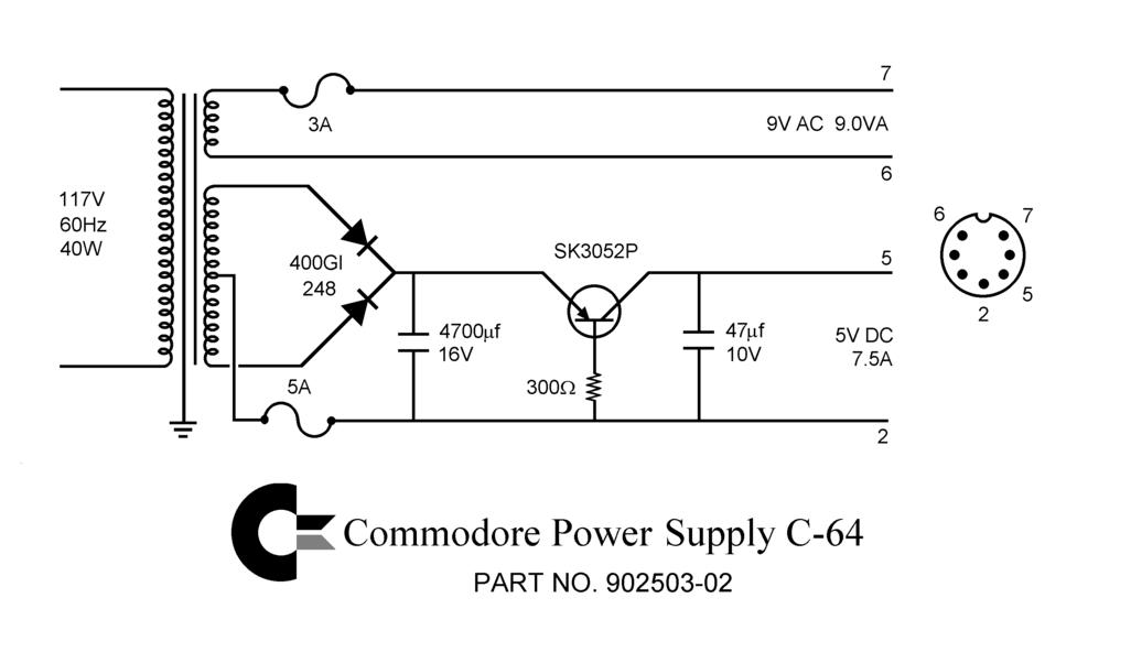
Pin 5 to the black cable (+5v)
Pin 2 to the green/yellow striped cable (-5v)
Pin 7 to the blue cable (9v AC)
Pin 6 to the brown cable (9v AC)
 |
| source: www.retroleum.co.uk |
Testing is tricky, the DIN connector is not really great for sticking probes in to so be very careful - its best to check without the hood of the din connector on. However, even if you have stuck the hood on, you should be able to check with your multimeter that you have 5v on pin 5, 2 and 9v AC (remember to put your multimeter in AC mode!) It's essential to check you have the right values at the right pins, cause any mistakes and your C64 could be damaged.
Step 5 is to fix the DIN plug's hood snugly over the pins, and affix in whatever way your particular DIN connector affixes. Then heat shrink all your heat shrinks if you're happy!

And thats it! I hope you now have a decent PSU for your Commodore 64.
No comments:
Post a Comment